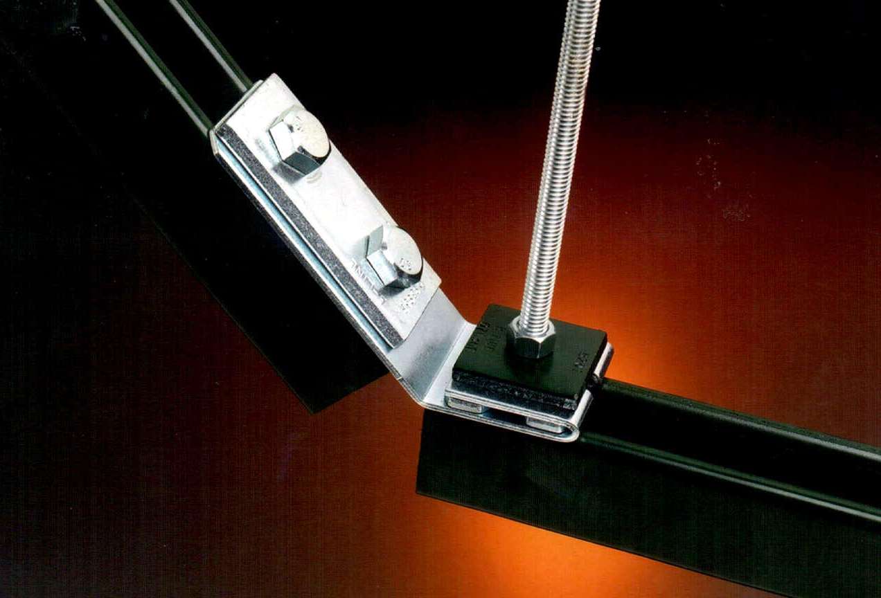

Brace angles from the horizontal should not exceed 60 degrees.Wire rope should not be in contact with anything along the brace length.Braces should always be installed as opposing pairs.Coil excess wire and secure to the main brace, if necessary trim excess leaving 150 mm tail. Feed wire back into Zip-Clip seismic locking device.Ĩ. Loop wire through the available hole in the retrofit bracket and position PVC sleeve against the through-hole.Ħ.

Pass wire rope through the Zip-Clip seismic locking device.ĥ. Ensure seismic restraint washer is included, and bracket orientation is in-line with the brace.ģ. Fit retro-fit bracket to existing primary support. Attach seismic bracket to ceiling structure with appropriate anchor as per manufacturers instructions, and structural engineers recommendations.Ģ. Restraint washer – steel, geomet finish.ġ.Retrofit bracket – steel, geomet finish.Wire locking device – Zinc alloy (ZAMAC5).A selected length of steel wire rope – 7×7, 1960N/mm² grade for R-System and B-System and 7×19, 1960N/mm² grade for GY-System.Seismic anchor bracket – steel, geomet finish.Third-party certification is available for strength and seismic tests. ICC ES AC156, acceptance criteria for seismic certification by shake table testing of non-structural components.IEEE 344-2013, standard for qualification of equipment for nuclear power generating stations.The GY-System range of seismic braces is designed for medium/heavy duty brace applications.Īll systems can be used as a seismic brace solution for new or retrofit installations to non-structural components.įor details on the capacities of the different systems request a copy of our latest Design Guide by emailing tested:.The B-System range of seismic braces is designed for light/medium duty brace applications.


 0 kommentar(er)
